
EN / FR
Request a Quote
WELCOME TO THE TOOL BENCH — PULL A DRAWER, LIFT OUT A TOOL, PUT NUMBERS ON IT.
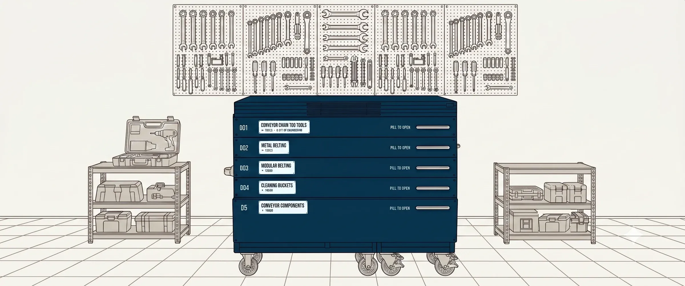
PICK A DRAWER — THEN LIFT OUT THE TOOL YOU NEED
Pull the chain taut. Measure over 12 pitches, pin-center to pin-center. Standard: plan replacement at 3% elongation — 1.75% on large or precision sprockets.
Head and tail sprocket. Pitch, teeth and target centers — get total chain length in even pitches and the exact centre distance it produces.
Pitch × teeth × RPM. Check linear speed against lubrication and drive limits.
Bring whatever you can measure — pitch, sidebar height, sidebar thickness, roller diameter — and it will narrow the field live until one chain remains. In build now; meanwhile, send us a photo and your numbers and we'll identify it same-day.
Balanced weave, compound balanced weave and flat wire. Pick the belt style, then a standard size from our catalogue — or type its spec code, e.g. B48-48-16-16 — and the pitch and wire sizes fill in. Measuring an unknown belt? Choose Custom and enter what you read with calipers.
Turn ratio is inside radius ÷ belt width. It sets which belt can make the turn, and how hard the outer edge has to work. The figure shows exactly where to take each measurement — click a field and it lights up on the drawing.
In a low-tension spiral the cage runs slightly faster than the belt it carries. That margin — overdrive — is what keeps inner-edge tension low. Too little and the belt drags; too much and you polish the edge. The figure shows exactly where each measurement is taken — click a field and it lights up.
The calculation every supplier manual is built around. Work out the pull, then check it against the rated strength on whichever datasheet you have.
Belt pull carries straight over from Tool 01. Sizes the motor, the shaft and the sprocket set.
Plastic belts move with temperature — a lot more than steel. Freezer to washdown, ambient to oven: this is how much length and width you have to design for.
Same measurements as a metal spiral, different limits. Plastic radius belts need a far wider turn than steel mesh, and the overdrive window is narrower.
The question everybody asks. The catenary is the slack loop on the return side — it is the belt's take-up. Too little and thermal growth has nowhere to go and the belt jumps sprockets; too much and it drags. The figure shows exactly where to measure.
Water level capacity is the engineering basis — Maxi-Lift and Tapco both calculate from it. Enter the bucket off any catalogue page and get bushels, cubic feet and tons per hour.
Whether a leg throws centrifugally or discharges continuously comes down to one number — the pole distance. Compare it to the head pulley radius and the answer falls out.
Lift the material, then add what the leg costs you — Maxi-Lift publishes 25% minimum for drive losses and up to 15% for friction and cup digging through the boot. Both are editable here.
Before you order: does the bucket fit the belt, clear the casing, and leave room to discharge? And will the belt carry the pull?
Pick a bucket and belt, enter what you know about the leg, and this tool checks whether the belt can carry the load. Don't have every number? Defaults are set from industry standards — just change what you know. The math follows Maxi-Lift's published method: belt weight + bucket weight + material weight + digging add-on = total tension, divided by belt width = workload PIW, compared to the belt's rated PIW.
Pick any two elevator buckets — same manufacturer or cross-brand — and compare every dimension, weight, and capacity spec side by side. The tool highlights which bucket has the advantage on each metric so you can choose with confidence.
Generate a dimensioned punching approval drawing — pick a bucket, set belt and mounting, get a live SVG with print, email and RFQ.


| Belt Type | |||
| Belt Width | Belt Length | ||
| Vertical Bucket Spacing | |||
| Pattern Style | Bolt Dia | ||
| Hole Spacing 1st Row | End Distance | ||
| Number of Holes | Row Count | ||
| Bucket Type & Size | |||
| Arrangement | |||
| Special Instructions | |||
| Customer | Date | ||
| PO # | SO # | ||
The same configurator as on our conveyor rollers page — open it below to build a roller to order.
Pick a series, then work through bearing, tube, shaft, sleeve and grooves. The tool returns the reference length to order by, a dimensioned schematic and a catalogue part number you can print or send straight to us.
13 series · Uniking Canada Rollers and Drive Rollers Catalog 2023The rule that keeps product tracking straight: at least three rollers under the load at all times. Pitch follows from your shortest product, and load per roller follows from pitch.
Conveyor speed into roller RPM, and the drive geometry that follows from it.